Testing a Thermal Fluid Loop with Simulation and Embedded Control
Follow a simulated fault from the controller's observations through its commands to the temperatures that actually result.
A controller’s shutdown request does not guarantee that a machine stops adding heat. Virtual Thermal Fluid Lab makes that gap inspectable: when circulation or heat rejection fails, what does the controller observe, what does it request, and what happens to the modeled temperatures?
I chose a small circulation bench to connect conservation equations, embedded control, and an interface for investigating evidence. A Python plant runs against an actual C controller executable. Raw traces let a reader follow the same experiment in a browser. The temperatures describe assumed equipment; they are simulated values.
I authored the tank starter, chose the project direction, and asked Codex to expand it into a thermal and firmware portfolio project. Codex drafted much of the code, specifications, and review material. Bounded implementation tasks and separate read-only reviews challenged equations, timing, and false passes. The repository exposes those decisions and executed checks. No rig fabrication or board execution is claimed.
The source and release evidence include requirements frozen before the campaign, failed checks retained during development, and native Windows reproduction instructions.
A model small enough to check
I kept the atmospheric tank benchmark: metered inflow minus a gravity drain changes its level. Constant fill, analytic drain, actuator lag, and empty/full event times have independently calculable answers. Its stuck-pump case already showed the central problem: a zero-inflow request cannot stop a failed actuator from filling the tank.
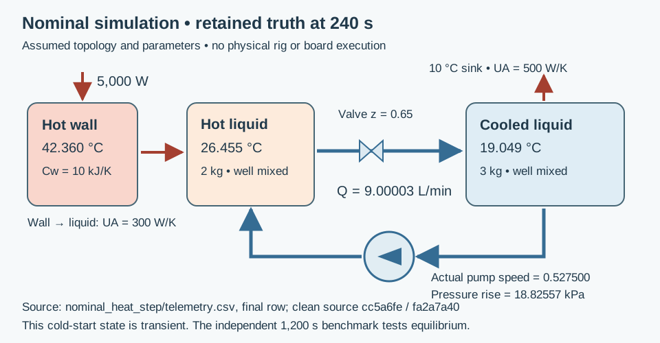
The thermal extension has three energy stores: a heated wall, a mixed hot liquid inventory, and a mixed cooled inventory. Equal forward flow exchanges liquid between the inventories; the cooled side rejects heat to a constant-temperature sink. Mass, density, and heat capacity remain constant. Pump and valve responses have assumed first-order lags.
Cw dTw/dt = P - UAh (Tw - Th)
Ch dTh/dt = UAh (Tw - Th) + rho Q cp (Tc - Th)
Cc dTc/dt = rho Q cp (Th - Tc) - UAc (Tc - Ts)
Every right-hand term is power in watts. Adding the equations cancels internal exchange and circulation, leaving imposed heat minus rejected heat. This follows control-volume energy-balance reasoning; the coefficients remain project assumptions.
Flow comes from the intersection of an assumed pump curve and loop resistance:
Pump pressure rise: p0 x² - Kp Q²
Loop pressure drop: (Kpipe + Kvalve/z²) Q², for z > 0
Here x is normalized pump speed and z normalized valve opening. Kvalve is an assumed pressure-resistance coefficient in Pa·s²/m⁶. Closure has an explicit zero-flow branch. This quadratic approximation cannot predict cavitation, water hammer, or pump efficiency.
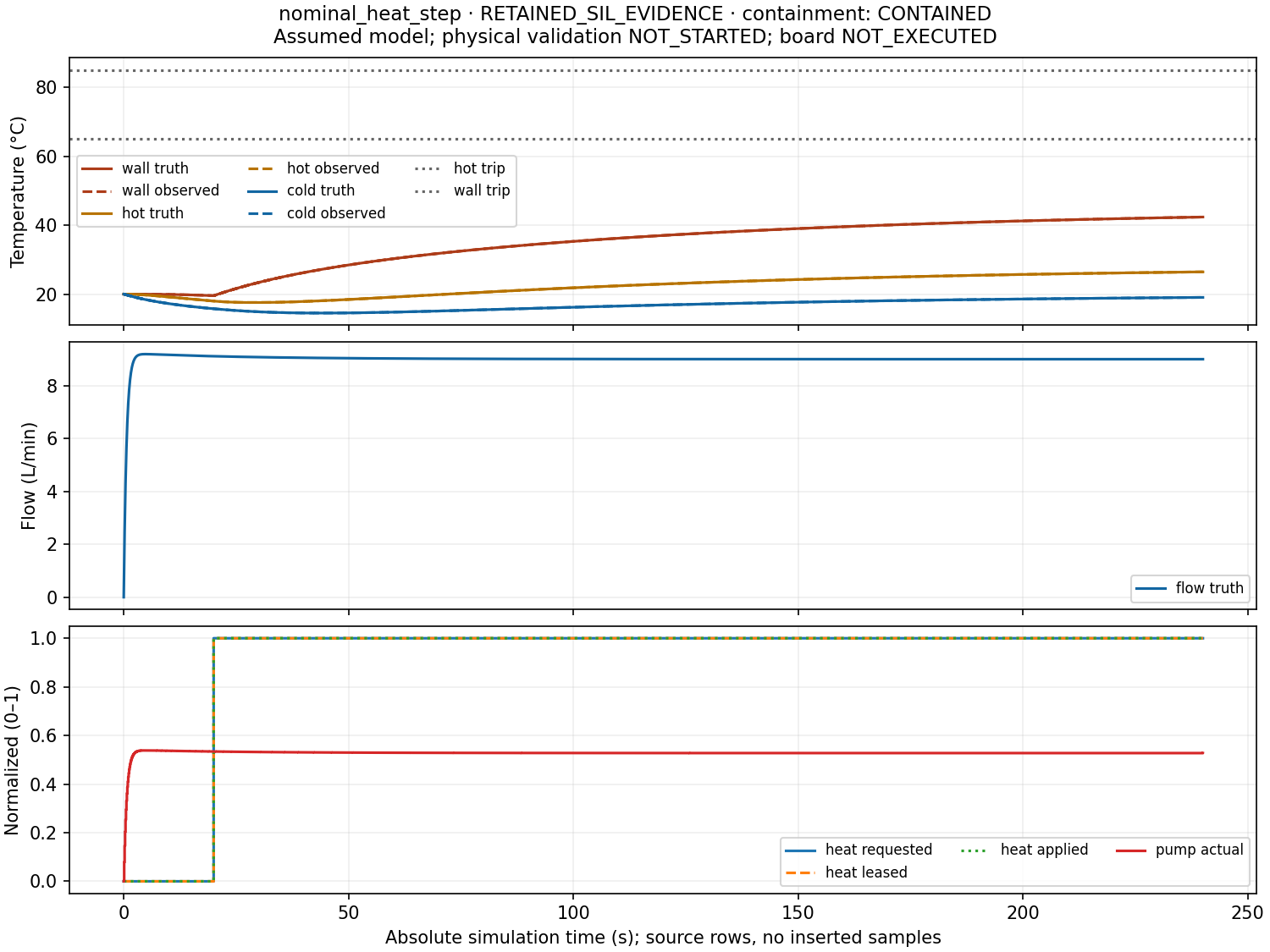
At the assumed 9 L/min target and 5,000 W input, independently derived steady temperatures are approximately 20 °C cooled liquid, 27.97 °C hot liquid, and 44.64 °C wall. The equilibrium test runs for 1,200 simulated seconds; a 240-second cold start still contains a substantial transient.
One controller core, two execution environments
The portable C11 core contains PI control, saturation and anti-windup logic, and a latched supervisor. It receives observed channels and their validity and age. Plant truth and fault labels stay outside its interface.
Shutdown depends on topology. The tank requests pump-off while preserving drainage. The thermal loop requests heat-off, full circulation, and an open valve. Requested commands, live leases, fault-modified inputs, and actual actuator states are separate fields. An acknowledgement records accepted intent; it cannot prove circulation or heat removal.
The same core source compiles into Windows/Linux executables and both Pico firmware images. The target adds monotonic time, timer scheduling, ADC/GPIO acquisition, USB serial, watchdog handling, and overrun counters. Its synthetic-link image supports both model profiles; its peripheral image uses an illustrative tank input and an onboard indicator.
Windows and Linux cross-builds demonstrate target compilation. Board execution remains NOT_EXECUTED. ADC accuracy, USB behavior, watchdog resets, and physical timing require captured board evidence. Simulation time, host wall time, and device time remain distinct.
Investigating a synthetic fault
A plausible frozen temperature can arrive with fresh timestamps. Freshness checks alone cannot distinguish a frozen sensor from a stable temperature. The campaign holds primary hot and wall readings constant while modeled temperatures rise after loss of heat rejection. The discriminating signal is a separately emulated temperature switch. On its trip, the controller latches heat-off and maximum cooling requests; the recorded actuator path shows whether those requests take effect.
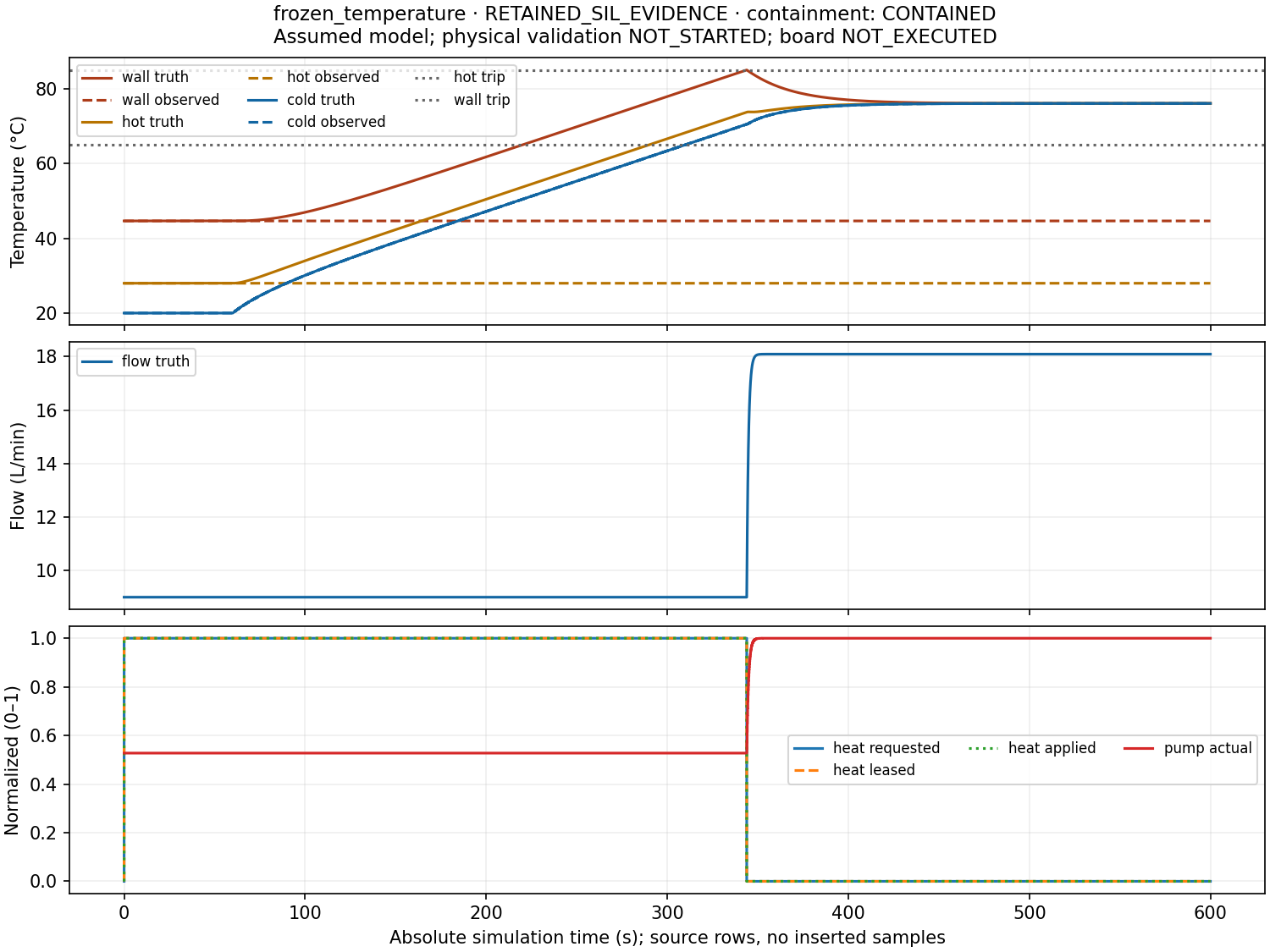
The frozen and biased cases trip through that switch at 343.9 seconds. Their conservative maximum-temperature bound is 85.059 °C, below the chosen 86 °C criterion, excluding numerical integration error. These are successful software containment tests under the assumed model.
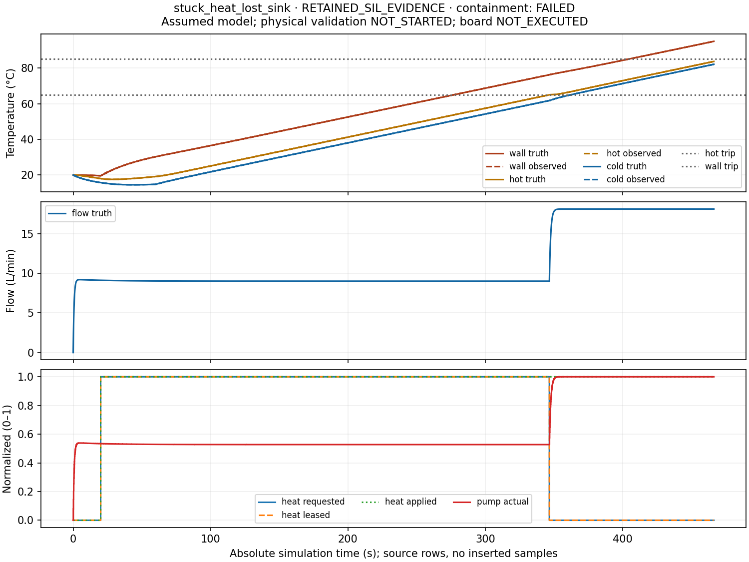
The deliberately uncontained case combines a stuck 5,000 W input with zero sink conductance. Before execution, the energy balance predicts a weighted mean rise of about 0.162 K/s, irrespective of circulation. Under the declared starting conditions, at least one temperature must reach the 95 °C model boundary by 585.3 seconds absolute.
The actual simulated controller trips at 346.6 seconds. Applied heating continues until the wall reaches the boundary at 466.299590 seconds. Integration stops there and preserves the fractional terminal snapshot. An expectation passes because the experiment exposed the predicted hazard; containment remains FAILED and the requested 1,200-second horizon is incomplete.
Inspect the evidence
The static replay shares a cursor across temperatures, flow, commands, actuator state, and events. It exposes truth versus observations, breaks stale or invalid observation lines, and compares scenarios on absolute time. Full-resolution CSVs, summaries, transport captures, and manifests remain downloadable.
The exporter verifies hashes before packaging. The viewer presents the evaluator’s recorded verdicts and explanations. Peak bounds show their exact coverage; a stopped run does not imply evidence for an unexecuted horizon.
What the checks establish
Independent heating, cooling, equilibrium, pressure-substitution, and boundary oracles check the numerical implementation. Solver-tolerance refinement is separate from changing the controller tick. Reviews caught a misleading convergence check: identical 95 °C terminal peaks could hide different trajectories. The repaired check compares a shared preterminal grid and boundary times separately. The 0.10/0.05-second thermal boundary times differ by 0.000774 seconds.
A clean native Windows checkout passed 135 unit tests, host/device CTests, seven preserved Python tank scenarios, ten thermal benchmarks, the full 17-case thermal and seven-case C tank campaign, and a byte-identical nominal repeat. All 36 refinement runs passed. A separate schema and artifact audit checked 48 thermal exports, 157,182 rows, and 484 hashes. Windows/MSVC, Linux/GCC, Linux sanitizers, and Pico cross-build CI passed at the verified runtime revision.
The selected 240-second demo completed in 8.43 wall seconds, about 28.5 times simulated speed, with 465.2 MiB summed from observed process lifetime peaks. The owning Python worker and C process were observed; short-lived descendants and final growth can escape discovery. This meets the chosen laptop demo budget, without establishing a strict unseen-process memory bound or hard real-time behavior. The separate full campaign took 198.1 seconds. Commands, hashes, and limitations accompany the release.
Physical validation remains NOT_STARTED. The model omits fluid transport delay, local gradients, phase change, and pump dissipation. Its cutoff and control thresholds are educational choices, with no physical safety certification.
The next useful experiment is an indicator-only Pico capture of acquisition, arming, latching, reconnects, and device timing. An ambient-water rig would separately measure geometry, sensor response, drain behavior, and pump flow, reserving whole experiments as holdouts. A thermal experiment needs its own reviewed fixture and instrumentation. Those measurements could expose where this compact model needs to change.